
Key takeaways
- The Variable Magnetic Field Module applies an in-plane (0–3000 G) or out-of-plane field to the sample while it is imaged in MFM, so domain switching is followed in situ.
- The field comes from two rotating permanent-magnet rods: no coil current, no sample heating.
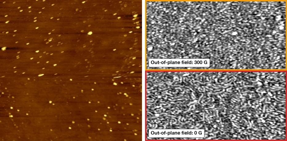
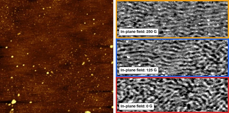
- Magnetic structures followed from 50 to 470 G show the rotation of domains and domain walls; on a thin magnetic film, the field was changed within a single scan (300 → 0 G out of plane; 250 → 125 → 0 G in plane).
- EFC removes the electrostatic contribution, so the MFM signal is magnetic only.
Introduction
Why image magnetism under a field
Magnetic force microscopy (MFM) shows the domain structure of a sample as it is. Many questions — how domains nucleate, how domain walls move, at what field a structure switches — need the domains to be seen while an external field changes. This note shows MFM with the Variable Magnetic Field Module (VMFM) of the Nano-Observer AFMs, in both field configurations.
Method
MFM and the Variable Magnetic Field Module
MFM is a two-pass technique: the magnetic tip first records the topography in resonant mode, then retraces it at a lift height of 10–200 nm and records the phase shift of the cantilever, which follows the magnetic force gradient. Lateral resolution is below 20 nm, depending on the tip.
The VMFM generates the field with two unbalanced magnetic rods rotated by a stepper motor — no current flows, so the sample is not heated as with a coil. With one rod below and one above the sample, the field crosses the sample out of its plane; with both rods to the side, the field lies in its plane, from 0 to 3000 G. Samples up to 15 mm in diameter and 10 mm high are accepted, and the module is compatible with HD-KFM, EFM and sMIM.
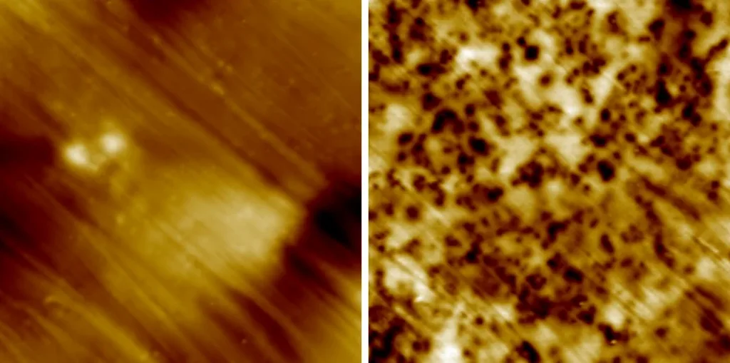
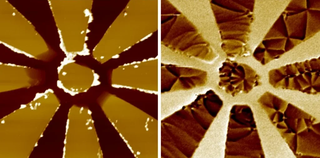
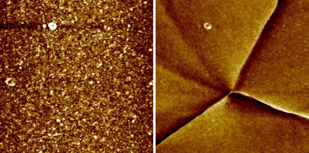
EFC (Electric Field Cancelling) compensates the electrostatic force acting on the lifted tip, so the MFM image shows magnetic contrast only (Figure 1).
Results
Magnetic structures from 50 to 470 G
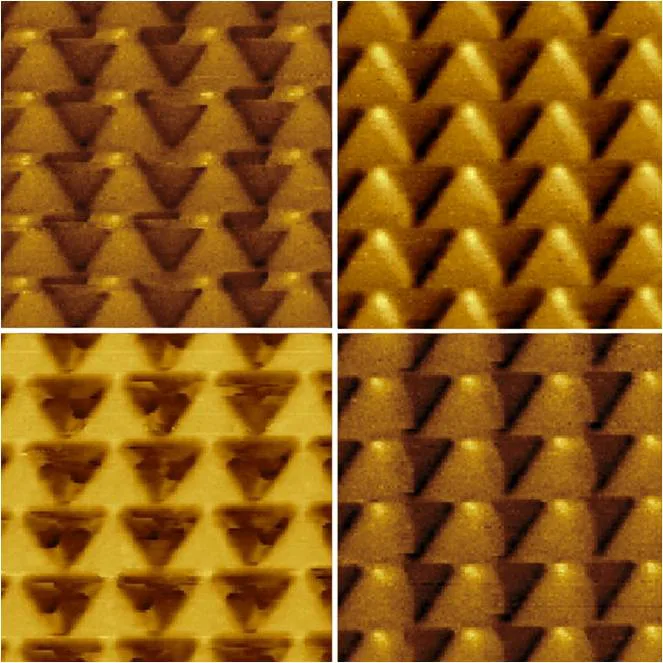
Figure 2 follows magnetic triangular structures while the in-plane field is increased from 50 to 470 G: the domains and domain walls rotate as the magnetization reverses.
Results
Field changed during the scan: thin magnetic film on silicon
On a thin magnetic coating on silicon, the field was changed while the image was being recorded, so each part of one MFM image corresponds to one field value. Out of plane (Figure 3), the upper half was scanned at 300 G and the lower half at 0 G; in plane (Figure 4), the top at 250 G, the middle at 125 G and the bottom at 0 G.
Results
Patterned devices
MFM resolves the magnetic contrast of patterned permalloy devices from the 20 µm overview down to a 4 µm close view (Figures 5 and 6).
Summary
Conclusion
MFM with the Variable Magnetic Field Module shows magnetic domains while the applied field changes — in plane up to 3000 G or out of plane — without heating the sample. Field steps can be applied within a single scan, domain and domain-wall rotation can be followed across a field range, and EFC keeps the image free of electrostatic contributions. Combined with HD-KFM on the same sample, magnetic and electrical domains can be compared directly.
In this note
AFM modes used
FAQ
Frequently Asked Questions
How does MFM image magnetic domains?
MFM is a two-pass technique: a magnetically coated tip first records the topography, then retraces it at a set lift height (10 to 200 nm) and records the phase shift caused by the magnetic force gradient. Lateral resolution is below 20 nm, depending on the tip.
How can a magnetic field be applied during MFM imaging?
With the Variable Magnetic Field Module (VMFM): two unbalanced magnetic rods, rotated by a stepper motor, apply a field to the sample while it is imaged. Depending on how the rods are placed, the field is in the plane of the sample (0 to 3000 G) or out of its plane.
Does the VMFM heat the sample?
No. The field comes from permanent magnetic rods, not from a coil, so there is no current-induced heating of the sample.
Can the field be changed during a single scan?
Yes. In the results shown here the field was changed during the scan — 300 G then 0 G out of plane, and 250, 125 then 0 G in plane — so each region of one MFM image corresponds to one field value.
How are electrostatic artefacts removed from MFM images?
With Electric Field Cancelling (EFC), which compensates the electrostatic tip–sample force so that the MFM signal shows magnetic contrast only.
What sample size does the VMFM accept?
Samples up to 15 mm in diameter and 10 mm in height. The VMFM can be combined with HD-KFM, EFM and sMIM.
Questions about MFM under magnetic field?
Ask the application scientists behind our AFMs and modes — about your samples, probes, set-up or which mode fits your measurement. We answer every message personally.